ASME B18.2.2 TABLE 1-1 Standardmäßig Abmessungen für Square nuts, square machined nuts and heavy square nuts, inch series
Gedrehte Vierkantmuttern und Sechskantmuttern
Maßzeichnungen und technische Diagramme
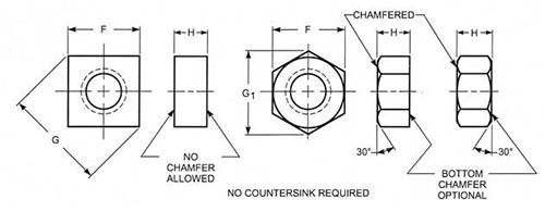
Wichtigste Abmessungen und technische Parameter
|
Dimensions in inches (1 inch=25.4 mm) sourceASME B18.2.2 table 1-1 Publication date: 2010 |
||||||||||
|
Nominal size or basic thread diameter
|
UNC (nr of threads x inch) |
UNF (nr of threads x inch) |
F basic | G min | G max | H min | H max | G1 min | G1 max | |
| inch | mm | |||||||||
| 0 (0.060) | 1.52 | - | 80 | 0.156 | 0.206 | 0.221 | 0.043 | 0.050 | 0.171 | 0.180 |
| 1 (0.073) | 1.85 | 64 | 72 | 0.156 | 0.206 | 0.221 | 0.043 | 0.050 | 0.171 | 0.180 |
| 2 (0.086) | 2.18 | 56 | 64 | 0.188 | 0.247 | 0.265 | 0.057 | 0.066 | 0.205 | 0.217 |
| 3 (0.099) | 2.51 | 48 | 56 | 0.188 | 0.247 | 0.265 | 0.057 | 0.066 | 0.205 | 0.217 |
| 4 (0.112) | 2.84 | 40 | 48 | 0.25 | 0.331 | 0.354 | 0.087 | 0.098 | 0.275 | 0.289 |
| 5 (0.125) | 3.18 | 40 | 44 | 0.312 | 0.415 | 0.442 | 0.102 | 0.114 | 0.344 | 0.361 |
| 6 (0.138) | 3.51 | 32 | 40 | 0.312 | 0.415 | 0.442 | 0.102 | 0.114 | 0.344 | 0.361 |
| 8 (0.164) | 4.17 | 32 | 36 | 0.344 | 0.456 | 0.486 | 0.117 | 0.130 | 0.378 | 0.397 |
| 10 (0.190) | 4.83 | 24 | 32 | 0.375 | 0.497 | 0.53 | 0.117 | 0.130 |
0.413 |
0.433 |
| 12 (0.216) | 5.49 | 24 | 28 | 0.438 | 0.581 | 0.619 | 0.148 | 0.161 | 0.482 | 0.505 |
|
1/4 (0.250)
|
6.35 | 20 | 28 | 0.438 | 0.581 | 0.619 | 0.178 | 0.193 | 0.482 | 0.505 |
|
5/16 (0.312)
|
7.94 | 18 | 24 | 0.562 | 0.748 | 0.795 | 0.208 | 0.225 | 0.621 | 0.65 |
|
3/8 (0.375)
|
9.53 | 16 | 24 | 0.625 | 0.833 | 0.884 | 0.239 | 0.257 | 0.692 | 0.722 |